CNC Lathe Turret Alignment Procedure: 10 Steps
Did you feel difficulty in the alignment of the CNC Lathe Turret? In this blog, you can find the best and easiest way to align CNC Lathe Turrent in just ten simple Steps.
What is CNC Lathe?
A CNC lathe is a device that turns fabric around an imperative spindle and stationary slicing tool. Your Material motion can be controlled by coded instructions fed via a laptop as an operator to operate with guide labor. A CNC lathe gadget is most commonly used to perform/produce precise spherical shapes with both direction an outer diameter (od) and an inner diameter (identity). Almost all types of structures can be machined with this device, depending on their needs in their respective industries.
CNC stands for Computer Numerical Control digitized statistics. A laptop and cam software is used to govern, automate, and reveal the movements of a machine. The gadget may be a milling device, lathe, router, welder, grinder, laser or waterjet cutter, sheet metal stamping system, robotic, or many other types of machines.CNC lathe machines or CNC turning machines are system gear that rotates a bar of material, allowing the slicing device to do away with cloth from the bar until the preferred product is last. The material itself is secured to and turned around the primary spindle while the slicing tool moves alongside more than one axis.
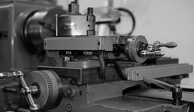
The turret is usually used on CNC lathes utility to preserve distinct forms of equipment for turning packages. It includes three pieces, phase gear coupling that permits the device disk to be indexed without lifting. It additionally guarantees excessive repeat positioning accuracy and pressure. A turret lathe is a form of metalworking lathe that is used for repetitive production of reproduction elements, which via the nature of their slicing systems, are generally interchangeable.
Turret Alignment – A Brief Intro to Why It Get’s Misaligned and How to Align it Back
Lathe turret alignments emerge as important for many motives. Device crashes are the simplest motive for desiring a turret alignment. They make sure that they run parallel with the z-axis, in addition, to cut on the middle with the component. If both alignments are out, Excessive tool put on or breakage will occur as well as sizing problems. This is why a properly aligned turret is important to any machining method.
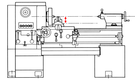
For this turret alignment method, you will want a magnetic base and a trademark. First, check the squareness of the turret by mounting the indicator in a place wherein you can sweep throughout the face of the turret. The indicator machine tool turret frame alignment should now not flow while this axis is moved. If it does, you will attempt mounting it on the tailstock, sub-spindle, or main spindle. In widespread, this must be underneath. In case you appear the alignment. Relying on the tolerance of elements will decide if it’s necessary to perform an alignment. If the lathe is doing middle drilling, this alignment is much greater critical. While a machine is crashed, the metallic can end up distorted, so you might also need to check multiple stations to affirm you are aligning it to the average tool face. This test examines that the turret face is parallel to the z-axis slide. This could affect how genuine your drills and dull bars run.
A Common Way to Diagnose The Misalignment
(1) mount an indicator to the chuck face or spindle nostril face, With the indicator factor towards the face of the turret.
(2) flow the x-axis up and down and look at the quantity of deviation along the face of the turret where the indicator is touching.
This type of misalignment could be much like the headstock misalignment we discussed in the ultimate submission. Because the headstock is normally bolted onto the base, The turret meeting can be bolted onto the x-axis slide. Because the illustration indicates, Turret misalignment that is detected at some point of the diagnosis. It can be constant utilizing loosening the keep down bolts as shown and moving the turret round until the alignment is repaired very, just like the headstock alignment manner.
CNC machines are great at cutting precisely, producing high-quality cuts. However, they require precise alignment of the tool path to achieve these results. Most lathes have a turret mechanism that holds the toolpath. In order to properly align the turret, you must first know how to set the toolpath properly.
Step 1: Set the Tool Path
The first step in setting the proper toolpath is to set the Z-axis position of the turret. To do this, you must first set the X axis of the machine to 0. Then, you must move the Y axis until the desired height is reached. Using the appropriate software, you must enter the desired length of the cut. If the software does not allow for manual entry, you may use the “Auto” function.
Step 2: Adjust the X-Axis Position
Once the Z axis is set, you must now adjust the X axis. You must first ensure that the X axis is in zero, meaning that the X axis is aligned parallel to the X axis of the workpiece. Once the X axis is set to zero, you must then move the X axis in small increments until the toolpath reaches the desired height. If the software allows manual input, you may enter the desired length of the cut.
Step 3: Adjust the Y-Axis Position
Next, you must adjust the Y axis until the toolpath reaches its final destination. Again, if you are using auto-entry features, you should be able to select the desired length of the toolpath and click ‘Enter.’ Otherwise, you must manually adjust the Y axis until it reaches the desired height.
Step 4: Check the Toolpath
Finally, once you have adjusted the X and Y axes, you must check the toolpath. Make sure that the toolpath is straight and perpendicular to the X and Y axes. If it isn’t, you need to make adjustments.
Ten steps Procedure to align CNC Lathe Turret
Step-1
Before you start, make sure that the lathe is clean and tidy, Casting off the turret face from the turret body. Then remove the turret assembly by disconnecting the screw holding it to the headstock and removing the top cap (I used a flat-headed screwdriver). Turn down the speed of your lathe to about 10 or 15 rpm for best results and be patient with this step: it can take as long as an hour to get through all of the parts in the turret assembly, and the castings will need to cool before the next casting operation can proceed. Place the finished turret on the lathe bed, so the axis of rotation is vertical.
Step-2
Complete an overall visual check and then. Remove the taper pins on both facets of the curve coupling. If you are not sure how to do this, ask for help from any professional or a helper who knows how to do so safely before proceeding with the next step. Using a sharp-pointed object (elevation tool), lightly press down on the curve in a small area, holding it there for about 2 seconds until the material softens and bends a little bit more, then release the pressure as quickly as possible without losing control of the tool.
Step-3
Remove the face and body parts, and use a dial indicator to measure the height difference between each turret tool holder. The maximum distance should be between (0 – 3 mm). Test the pin length after each tool is installed into the tool holders, pressing it down firmly on a piece of scrap steel.
Step-4
Remove the face and body parts, and use a dial indicator to measure the height difference between each turret tool holder. Measurement of the height of each turret is important to determine how long to make each part before cutting it out from the material for your model.
The following information will be used as a guide:
1) For a basic 2-scale kit, you may have to make all of the turrets about 1/16th of an inch taller than the corresponding body pieces so that they are flush with the bottom of their respective bodies.
2) If your scale model is a larger one, like a 4- or 5-scale kit, then you might have to make the turrets slightly higher than the corresponding body pieces because if they were too close together, the lower body would get caught up inside the upper body, thus causing interference during assembly.
Step-5
Slightly loosening the keep-down bolts for the coupling halves. Using a new position angle (x) value of 2° from where we want to place our alignment tool, as this will move it slightly in front of the tool holder, so the laser spot is on top of the centerline of the tool holder slot/slit, which also moves it forward of the vertical guide rail that the bolt axis rests against when tightened down, but it still sits parallel to the axis of the nut and bolt holes through the two halves of the assembly, and the tool holder itself will need to be realigned at the same time.
Step-6
Remounting the turret face and physically shifting the turret, Till the precise identity tool holder alignment can be carried out. Reassemble the machine and test for repeatability and accuracy. If any of the turrets fail to meet tolerance during the test run, you will need to adjust the positions of the upper and lower face plates relative to the tool holder so that their heights are equal.
Step-7
Putting off the turret face again. There are many types of alignment tests that exist today, but we have chosen to focus on two main types; 1.) Vertical Alignment test 2.) Horizontal Alignment test You have to be sure about these two alignments behind the turret and ensure your machine runs safely and efficiently.
Step-8
Reaming all taper pin holes in line to smooth. Alignment testing can help improve safety, and productivity and reduce lost production time which can hurt profits – but the best thing is not having a part failure at all!
PEEK is a highly inert polymer that has very low friction and high tensile strength properties making it ideal for drilling and reaming operations where extreme accuracy of alignment is required and long wear life is needed, such as when machining the outer diameter of tapered pins or large flange hole diameters (eccentricity must be considered). PEEK is available in many grades, from a pure grade with no additives, through grades with anti-static agents and lubricants to grades with fillers and other additives.
Step-9
Next, Change the taper pins. Tightening up all coupling maintain on down bolts. The bolt you are referring to is not a “sleeve head” bolt but is a pin that goes through the sleeve head of the head stud into the bearing cap housing, where it fits into threading in the bore of the hub assembly housing where it tightens against an annular collar which prevents rotation or loosening of the stud on the axle housing when tightening nuts on the wheel end housings or hubs or when driving the vehicle over rough roads and terrain which could cause loosening of the stud from the wheel end housing causing it to come loose on the axle shaft and possibly damage the differential gearing system.
Step-10
Reassemble and recheck its position and work. Make sure every turret part is tightly fitted, and proper alignments are achieved.
If you are unhappy with your results, repeat steps 4-6 a second time, slowly rotating the turret while watching your indicator reading. You should see a smooth change in readings without any peaks or valleys. This only needs doing if some of your measurements are out compared to others.
Conclusion
So this is how you could align and restore your CNC lathe turret. Of course, we always suggest you employ a professional to restore the results or take help from it to build it successfully. But living within the actual global, we realize that on occasion, you cannot wait. We hope that the points and suggestions stated here can help you and help you to align it in a higher manner.

Hi, my name is Charles Winn, A DIY enthusiast, Mechanical Engineer. I was born and raised in Springfield, Missouri. I am also a father of two troublemaker kids, a terrible photographer, and I love to play chess.